Friday 6 May 2011

CRBT (Caller Ring Back Tone)


What is CRBT?
When person A calls person B, if person B is available, then person A hears a ringback tone! Now CRBT replaces that ringback tone with a selectable music. So, now, a person A dials person B, person A gets to hear a music, person B has selected as his CRBT Tone.


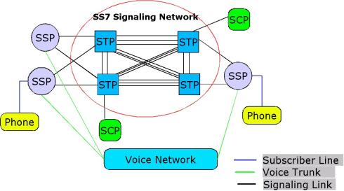
CRBT can be implemented various ways! The easiest way is using SS7 call routing and IVRS.


CRBT Call Flow
1. Switch receives a call from Subscriber A to Subscriber B.


2. Switch routes the call to IN ( Intelligent Network) System. IN System will check if subscriber B is available, if yes, it checks if Subscriber B is a CRBT Subscriber. If no, it sends back to the call to connect the call normally. If yes, it asks switch to dial out Subscriber B, while it transfers the call to CRBT Server, which is nothing but IVRS Server. As soon as IVR receives the call, it plays back the pre-programmed music as per caller id or the Subscriber B.

3. IN System keeps monitoring the switch dialing out to Subscriber B. As soon as Subscriber B receives the call, or disconnects it, IN system disconnects from CRBT Server, asks switch to connect subscriber A and Subscriber B.


            Sub A call to sub B
  1. A connect to MSC A.
  2. MSC A send IAM to MSC B.
  3. MSC B check information about Sub B in HLR B.
  4. HLR response to MSC B that sub B is active and use CRBT Service.
  5. MSC B send ACM to MSC A
  6. MSC B send IAM to CRBT system
  7. CRBT System check information (ANIS, DNIS ) in CRBT system and send ACM to MSC B.
  8. After that, CRBT System send ANM to MSC B
  9. From this time, CRBT System will play song and sub A can listen song.
  10. In this time, MSC B is paging Sub B.
  11. If Sub accept this call, Sub A and B will conversation, MSC B send REL to CRBT System.
  12. After that, CRBT send RLC to MSC B for finish connection with CRBT System


Thursday 5 May 2011

SS7 Protocol Suite

There are two essential components to all telephone calls. The first, and most obvious, is the actual content—our voices, faxes, modem data, etc. The second is the information that instructs telephone exchanges to establish connections and route the “content” to an appropriate destination. Telephony signaling is concerned with the creation of standards for the latter to achieve the former. These standards are known as protocols. SS7 or Signaling System Number 7 is simply another set of protocols that describe a means of communication between telephone switches in public telephone networks. They have been created and controlled by various bodies around the world, which leads to some specific local variations, but the principal organization with responsibility for their administration is the International Telecommunications Union or ITU-T.

Signalling System Number 7 (SS#7 or C7) is the protocol used by the telephone companies for interoffice signalling. In the past, in-band signalling techniques were used on interoffice trunks. This method of signalling used the same physical path for both the call-control signalling and the actual connected call. This method of signalling is inefficient and is rapidly being replaced by out-of-band or common-channel signalling techniques. 


SS7 Call Flow


ss7


SS7 protocol suite


The SS7 protocol stack borrows partially from the OSI Model of a packetized digital protocol stack.

SS7 Protocol layers:
The SS7 network is an interconnected set of network elements that is used to exchange messages in support of telecommunications functions. The SS7 protocol is designed to both facilitate these functions and to maintain the network over which they are provided. Like most modern protocols, the SS7 protocol is layered.

Physical Layer (MTP-1)
This defines the physical and electrical characteristics of the signaling links of the SS7 network. Signaling links utilize DS–0 channels and carry raw signaling data at a rate of 56 kbps or 64 kbps (56 kbps is the more common implementation).
Message Transfer Part—Level 2 (MTP-2)
The level 2 portion of the message transfer part (MTP Level 2) provides link-layer functionality. It ensures that the two end points of a signaling link can reliably exchange signaling messages. It incorporates such capabilities as error checking, flow control, and sequence checking.
Message Transfer Part—Level 3 (MTP-3)
The level 3 portion of the message transfer part (MTP Level 3) extends the functionality provided by MTP level 2 to provide network layer functionality. It ensures that messages can be delivered between signaling points across the SS7 network regardless of whether they are directly connected. It includes such capabilities as node addressing, routing, alternate routing, and congestion control.
SS7 layer architecture diagram
Signaling Connection Control Part (SCCP)
The signaling connection control part (SCCP) provides two major functions that are lacking in the MTP. The first of these is the capability to address applications within a signaling point. The MTP can only receive and deliver messages from a node as a whole; it does not deal with software applications within a node.
While MTP network-management messages and basic call-setup messages are addressed to a node as a whole, other messages are used by separate applications (referred to as subsystems) within a node. Examples of subsystems are 800 call processing, calling-card processing, advanced intelligent network (AIN), and custom local-area signaling services (CLASS) services (e.g., repeat dialing and call return). The SCCP allows these subsystems to be addressed explicitly.
ISDN User Part (ISUP)
ISUP user part defines the messages and protocol used in the establishment and tear down of voice and data calls over the public switched network (PSN), and to manage the trunk network on which they rely. Despite its name, ISUP is used for both ISDN and non–ISDN calls. In the North American version of SS7, ISUP messages rely exclusively on MTP to transport messages between concerned nodes.
Transaction Capabilities Application Part (TCAP)
TCAP defines the messages and protocol used to communicate between applications (deployed as subsystems) in nodes. It is used for database services such as calling card, 800, and AIN as well as switch-to-switch services including repeat dialing and call return. Because TCAP messages must be delivered to individual applications within the nodes they address, they use the SCCP for transport.
Operations, Maintenance, and Administration Part (OMAP)
OMAP defines messages and protocol designed to assist administrators of the SS7 network. To date, the most fully developed and deployed of these capabilities are procedures for validating network routing tables and for diagnosing link troubles. OMAP includes messages that use both the MTP and SCCP for routing.

GSM CALL FLOW

GSM is a cellular network, which means that mobile phones connect to it by searching for cells in the immediate vicinity. There are five different cell sizes in a GSM network—macromicropico,femto and umbrella cells. The coverage area of each cell varies according to the implementation environment. Macro cells can be regarded as cells where the base station antenna is installed on a mast or a building above average roof top level. Micro cells are cells whose antenna height is under average roof top level; they are typically used in urban areas. Picocells are small cells whose coverage diameter is a few dozen metres; they are mainly used indoors. Femtocells are cells designed for use in residential or small business environments and connect to the service provider’s network via a broadband internet connection. Umbrella cells are used to cover shadowed regions of smaller cells and fill in gaps in coverage between those cells.


The modulation used in GSM is Gaussian minimum-shift keying (GMSK), a kind of continuous-phase frequency shift keying. In GMSK, the signal to be modulated onto the carrier is first smoothed with a Gaussian low-pass filter prior to being fed to a frequency modulator, which greatly reduces the interference to neighboring channels (adjacent-channel interference).


Network structure

The structure of a GSM network
The network is structured into a number of discrete sections:

Flow Diagram